
Back to Know-How-Page
|
|
You are unsatisfied with the range of compatibility of your 3D glasses
controller?
You have some glasses without controller (like ASUS)?
Why not build your own for a few pennies?
Needless to say this is all "at your own risk" stuff.
last update:
June 10, 2003

|
|
| Shutterglasses Controller | Circuit | Comment | Literature |

serial/parallel port controller, (circuit is applicable for DIN-3 port too with little modification) |
circuit:
Tomi
Engdahl (www),
board-layout: Schuhmann
& Krause (english and german)
|
outdated
Click
here
for comment
|
"Virtual reality creations", The Waite Group (this book contains a serial/parallel circuit) |
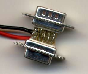
parallel/serial controller to DIN-3 adaptor |
parallel port controller
to DIN-3:
pin 4 to pin 3 (sync)
Thanks to
|
outdated
It's possible to use a par/ser
controller on the VESA3 miniDIN3 port by connecting the corresponding pins.
No electronics required, just wires and 2 plugs.
|
|
|
DIN-3 controller |
similar to the serial/parallel port controller circuit | for
connecting consumer glasses to a professional DIN-3 equipped VGA-board
just use a DIN-3 plug instead of a serial or parallel plug on designs above |
|
2-in-1-VGA-pass-through controller with auto-sync supports ELSA Revelator, ASUS and other page-flipping or interlace drivers as well as professional OpenGL flipping drivers |
Original
circuit by Martin Krysiak
Schuhmann
& Krause (english and german)
|
supports
many drivers, but I would rather go for the 3-in-1 design
Click
here
for comment
|
"Steps into virtual reality" by John Fovine , Mc graw Hill, ISBN-0-07-911906-9 (this book contains a VGA-p.-t. circuit) |
| 3-in-1-VGA-pass-through
controller with sync-doubler and auto-sync
supports nVidia, ELSA Revelator, ASUS, Wicked3D, eDim and other page-flipping, interlace or over-under drivers as well as professional OpenGL flipping drivers and professional over-under format applications |
Florian
Schreck, (not sure if this one does autosync too)
or Schuhmann
& Krause (english and german)
or |
this is the homebrew circuit of choice, unless you dare to try the new line blanker design (see below)! | |
| 4-in-1-VGA-pass-through
circuit with line blanker, sync-doubler and auto-sync
supports nVidia, ELSA Revelator, ASUS, Wicked3D, eDim, VRStandard and other page-flipping, interlace or over-under drivers as well as professional OpenGL flipping drivers and professional over-under format applications , also supports line-sequential drivers and materials |
Andreas
Schulz
Christian evil.moshi@gmx.de
|
The Video-Switch IC from
MAXIM (MAX 499) is capable of line blanking. It has two RGB inputs and
one RGB output. The chip interlaces the two RGB inputs. By using the VGA
signal as one input and a 0V "black" signal on the other Line-Blanking
functionality can be achieved.
Half the H-Sync frequency is used to switch between the two inputs and half the V-Sync frequency is used to invert the switching. |
|
|
Revelator/nVidia-VGA-pass-through cable |
not yet | ||
| Revelator/nVidia-VGA-pass-through controller for 3.5 mm stereo jack glasses (ASUS and the like) | not yet | ||
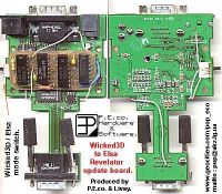
How to make the classic H3D/W3D controller Revelator/nVidia-compatible |
homebrew project page | a must have for classic-H3D owners! | |
| TV/Video controller | Tomi Engdahl | connects
between VCR and TV set
requires special Stereo3D video-tapes, DVD's or a 3D-camcorder add-on |
|

SimulEyes/miro fanatix to DIN-3 (or serial/parallel) |
circuit | Click
here
for comment
It should also be possible
to connect the SimulEyes controller (not the glasses directly) to the serial
or parallel port by a simple cable. No complex circuits required. See VESA-3
section. This makes sense since the White-Line-Code problem can be
overcome that way.
|
|
| classic H3D alternate controller | not yet | It might be possible to build a homebrew controller (par, ser, DIN-3, VGA-pt, sync-doubler) with a connector for the H3D infrared transmitter to increase software compatibility of the H3D glasses. The problem? We know nothing about the signaling of the H3D miniDIN3 port. H3D told me it's different from the VESA3 miniDIN3 signaling. (Thanks to Nik http://surf.to/eastfield for asking.) |
|
|
I had some discussions about the voltage for shutterglasses and did
some testing. I drove the original 3D-SPEX controller and a homebrew controller
at different voltages from 3 to 12 V, using 3D-Max and 3D-SPEX glasses.
They start working at about 4.5 V. At higher voltages the light blocking
is better. Anything up to 20V shouldn't cause permanent damage.
Jörg
Fischer told me the original SimulEyes controller shows an amplitude
of 19V. The original 3D-SPEX controller is driven by 12V. I have yet to
test the original 3D-Max and 3D-SPEX controllers on the oscilloscope (I
don't have one at home).
The original retail controllers seem to have at least two differences,
compared to the homebrew circuits currently available. First they shut
off the glasses completelely if there's no control signal, while with the
homebrew circuits one glass stays dark. Second the retail controllers seem
to discharge the glasses completetly at shut-down, while on homebrew controllers
the glasses may stay "foggy" due to some residue polarization structures.
Usually the glasses become clear again if they are activated again,
at the right voltage. At one point I had "fog" effects, which didn't vanished
on activation, especially when driving the controller on battery. In case
you encounter similar problems you might use a variable power adaptor and
try different settings.
|
|
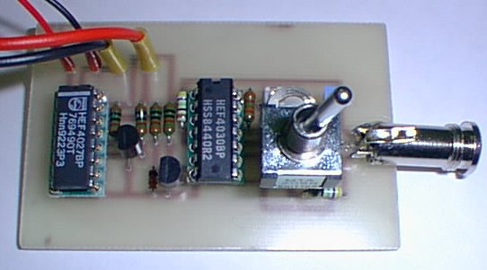
homebrew parallel controller build by Franz
Krause & Thomas Schuhmann
==================================================================
Florian's section start
==================================================================
Here are some very useful "Do it yourself" hints by Florian Schreck:
Comments on the "do it yourself" parallel./serial LCD-shutterglasses controller:
1) You can use Kasan 3D-MAX glasses with this circuit.
2) To make your glasses compatible with
the CyberBoy connect it to a
female 9pin sub-D connector (serial port) as follows.
The circuit
consumes only 1.2 mA, so it can easily be supplied with
power by
the serial port.
| female 9pin sub-d Pin Nr | do it yourself circuit |
| 4 | left/right |
| 5 | GND |
| 7 | power (glasses on/off) |
Use this sequence to start LCD-BIOS:
LCDBios /COM1 /LCDCtl:FC030200 /LockFlip /HRefresh
CyberBoy Serial Port Configuration
Serial 9 PIN Description
(N.C. : No Conection)
| Pin | PC | CyberBoy | Voltage Value |
| 1 | Data carrier Detect | N.C. | N.C. |
| 2 | Receive Data | N.C. | N.C. |
| 3 | Transmit Data | Power | -12V |
| 4 | Data terminal Ready | Glasses Signal | -12V ~ +12V |
| 5 | Signal Ground | GND | 0V |
| 6 | Data Set Ready | N.C. | N.C. |
| 7 | Request to Send | 3D Mode On/Off | -12V ~ +12V |
| 8 | Clear to Send | N.C. | N.C. |
| 9 | Ring Indicator | N.C. | N.C. |
3) To make your glasses compatible with
the NuVision 3D-SPEX connect
it as
follows to a 25pin male sub-D connector. Use a 9V Batterie
as power supply:
| male 25pin sub-d Pin Nr | do it yourself circuit | 9V power supply |
| 4 | left/right | |
| 18 | GND | GND |
| power | 9V |
It is also possible to connect it with the parallel port
with a printer cable.
In this case use the following connections:
| Centronix pin Nr | do it yourself circuit | 9V power supply |
| 4 | left/right | |
| 33 | GND | GND |
| power | 9V |
Use this sequence to start LCD-BIOS:
LCDBios /LPT1 /LCDCtl:FBFFFBFF /LockFlip /HRefresh
You can also use NUVFRAG
(e.g. for DOS-Quake)
4) To make a CyberBoy compatible "do
it yourself" circuit compatible with the
3D-SPEX use the following adapter (this
will not work with the original CyberBoy).
| Centronix pin Nr | 9V power supply | female 9pin sub-d pin Nr |
| 4 | 4 | |
| 33 | GND | 5 |
| 9V | 7 |
or the following:
| male 25pin sub-d pin Nr | 9V power supply | female 9pin sub-d pin Nr |
| 4 | 4 | |
| 18 | GND | 5 |
| 9V | 7 |
Have fun!
Florian Schreck
florian.schreck@uni-konstanz.de
http://ag-rempe.physik.uni-konstanz.de/privat/florian/lcd/index.html
==================================================================
Florian's section end
==================================================================
Most serial/parallel port shutterglasses systems
do not have a stereo reverse switch. In some programs this might cause
problems. Here's a way to switch the stereo orientation by software:
Switch eyes on LCDBios by changing the LCDCtrl:/AALLRROO
command.
Just swap the LL and RR numbers to reverse
stereo.
(Thanks to Don Sawdai and Gabor Laufer.)
|
|
Circuit for VGA-Pass-Through shutterglasses controller
Here's a comment by Martin
Krysiak on his VGA-pass-through circuit.
Martins hand-drafted circuit started it all. I removed the image of
the draft because of limited web-server-space.
There are now E-CAD rendered and printed circuits based on Martins
draft.
If you're interested in the original draft for any reason you can see
it here. (It's a 130 kB GIF).
Jörg Fischer and Michael Bosch did a nice new rendering of the
VGA-pass-through-controller,
complete with part-list.
There's
a printed circuit layout by Thomas Schuhmann & Franz Krause too.
| VGA-Pass-Through Controller Circuit Description
The vertical retrace signal is placed at the I/P of the gate of FET BF246B. This offers two advantages: a) In theory no current will flow between the gate and the source as FETs are voltage activated as opposed to bipolar transistors which are current activated. This ensures the integrity of the vertical retrace (V-SYNC) signal going to the monitor. b) The voltage level is amplified as some VGA cards have slightly lower V-SYNC levels and input logic levels may otherwise be compromised in terms of the circuit design and applied voltages. Because the vertical retrace signal form characteristic is not alway correctly interpreted by conventional input gate logic: NB (sometimes the ciruit misses a "TICK" and this results in the stereogram being reversed) a CD40106B SCHMIDT TRIGGER is invoked to provide a true form. It is essential that the shutterglasses (left and right LCD) remain
open/closed respectively during the respective and corresponding screen
exposures for the complete durations thereof to give precidence to this
a JK (?) flip flop is invoked in the toggle position.
= Full Vertical Retrace (one full screen of information) The Q output is then placed at the inputs of a 4011 where the final
outputs are determined/inverted/non inverted ext.
NB: It is important that the LCD's are completely darkened and the correct voltage applied to prevent for example: when the applied voltage is too low the LCD's will not polarize completely and image ghosting will result. |